Eliminating Clogged Feeding Tubes:
How the TubeClear System Works
Reusable
Control Box

Single Use
Clearing Stem

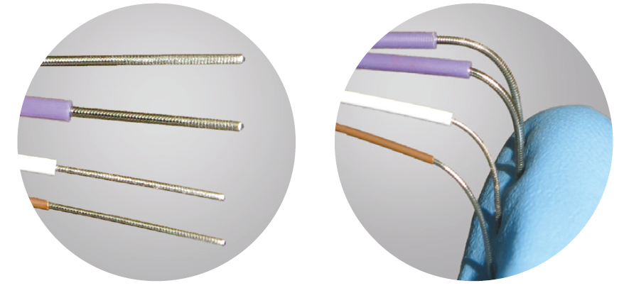
The Clearing Stem contains a specially designed flexible wire surrounded by a sheath. It connects to the control box at the diaphragm via a magnet. The wire moves back and forth to remove build-up and ultimately clear clogged feeding tubes.
The Clearing Stems are round, flexible Wires.
The Control Box contains a motor that moves the Clearing Stem Wire backward and forward very quickly inside the Clearing Stem. This movement mechanically breaks up and clears clogged materials while the feeding tube remains in the patient at bedside.

The operator moves the Clearing Stem backward and forward manually for maximum effectiveness. Various clog types require different techniques to achieve optimum effectiveness.
Clearing Stem Models
Selecting the Right Clearing Stem for Your Patient’s Feeding Tube
Read the entire Operator’s Manual before using TubeClear. Disregarding the cautions and instructions presented in this manual constitutes ABNORMAL USE.
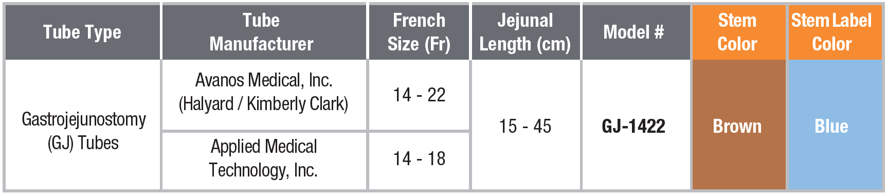
GJ-1422 Model

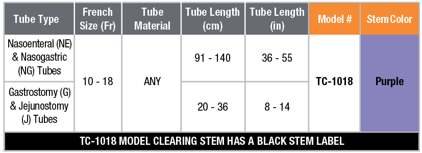
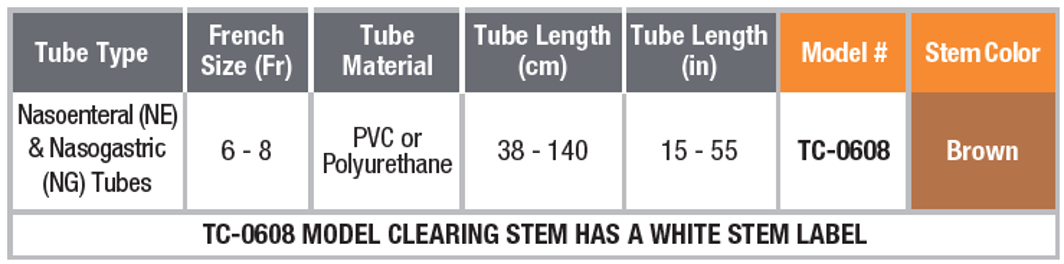
TC Models

Additional Clearing Stem Models

NE Models
The 10-18 Fr NE Clearing Stem Models feature a fixed Depth Marker and come in a variety of lengths to suit your patient’s feeding tubes. Please refer to the appropriate Directions for Use for more information including indication, contraindications, cautions, and warnings
G Models
The 10-18 Fr G Clearing Stem Models feature a fixed Depth Marker and come in a variety of lengths to suit your patient’s feeding tubes. Please refer to the appropriate Directions for Use for more information including indication, contraindications, cautions, and warnings.